|
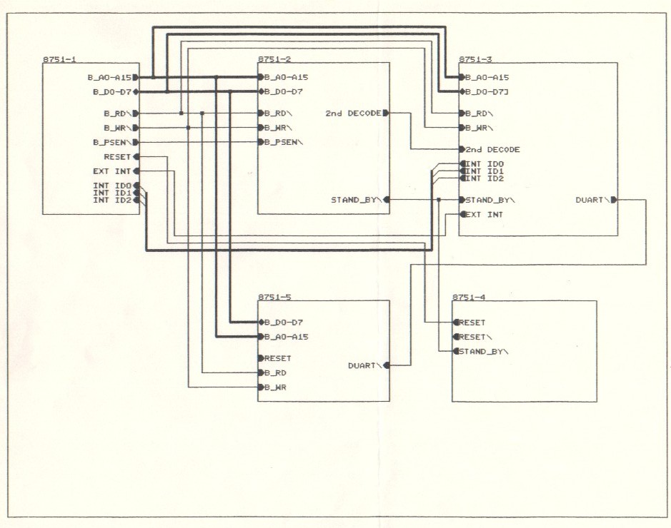
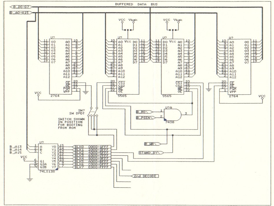
One of the first large scale 8051 projects I designed was a general micro-computer with a few telephony features. It used a generic 8031/8051, and external program memory. The entire program was written in assembly language and included routines to allow me to single step through the code, view disassembled code, and a host of other debug capabilities. I could download a new code image to battery backed up RAM, and reboot to test it. Booting from RAM vs. ROM was switch selectable.
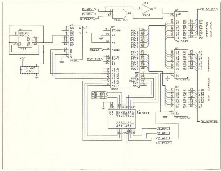
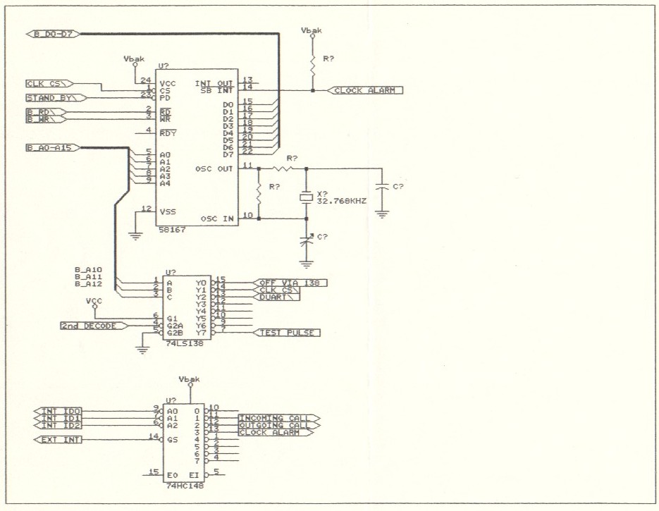
For a real time clock I used the National Semiconductor M58167. This IC had a rather long read cycle time, and the 8051 I used did not allow wait states. To get around this, I added the ability to run the processor at different frequencies, under software control. I could select one of two frequencies by setting the port 1 bits (2, 3 and 4) to the proper value so that the 74151 would select the signal at its D3 or D7 input (see schematic sheet 2). The routine to read from the clock would first lower the CPU frequency, read the clock, then return the CPU to its normal running speed.
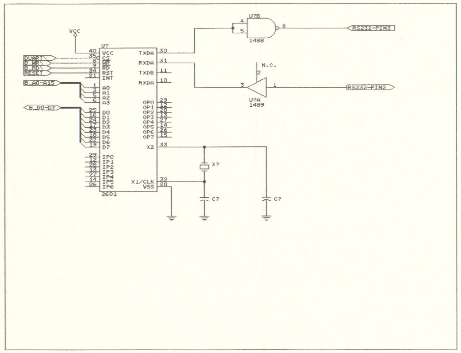
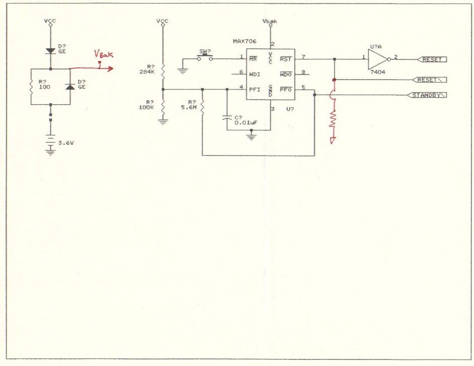
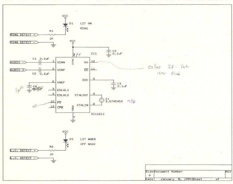
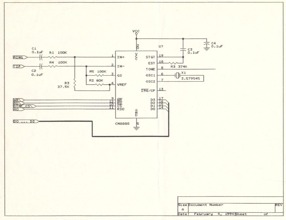
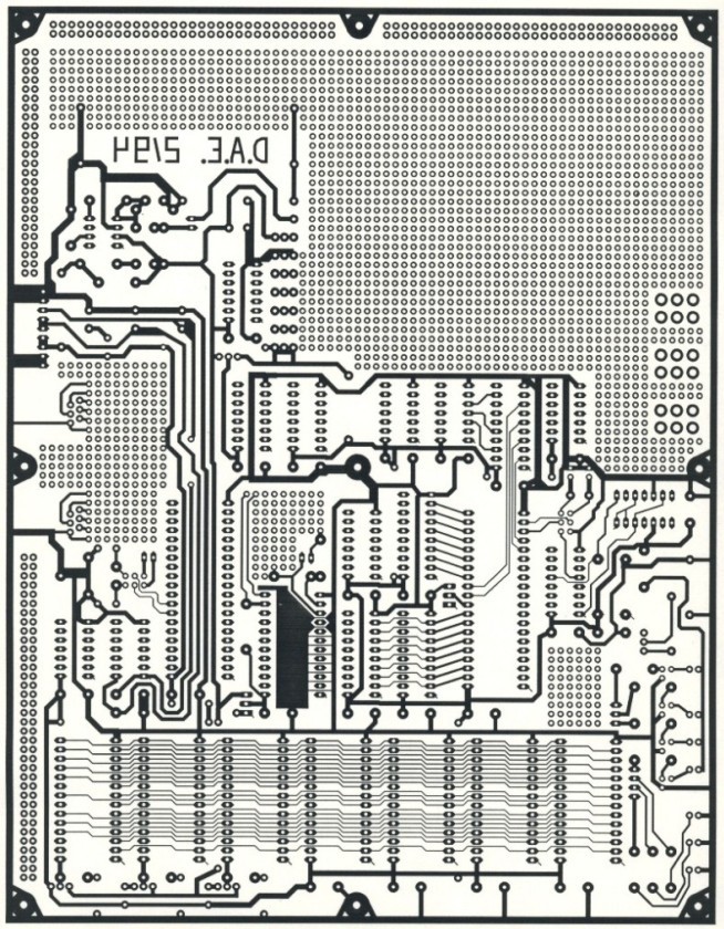
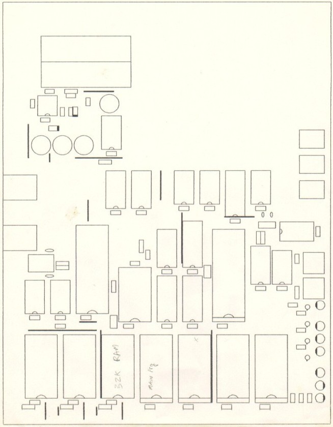
This project was also my first to take advantage of the new Caller ID technology. I used the SC11211CN Caller ID chip to capture Caller ID data, and read that in using one of the serial ports of the SCN2681 DUART. One of my goals with projects like this was to push myself away from building projects the way I always had - using only discrete TTL ICs. I also made use of the microprocessor supervisory IC MAX706 to provide the reset signal to the CPU, and the CM8888 DTMF transceiver to detect and generate DTMF tones. I was going to have a single layer printed circuit board made for this project (see PCB layout below). Unfortunately this never happened.
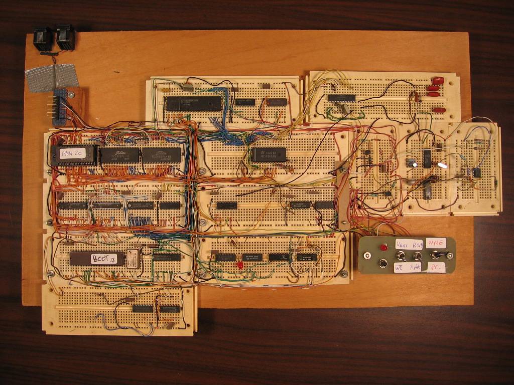
This project shows how I approached most of my projects. I'd start out with a piece of plywood, and screw down the modular IC breadboards. At one point I had nearly $250 worth of these boards. I bought so many because I'd have multiple projects going at once, and couldn't stand to tear one apart after I had spent so much time on it. I tried to build most of my projects to be all in one piece - the circuitry, power supply, switch panels, etc, all on a single easily transportable piece of plywood. My RIT 8088 project was a good example of this.
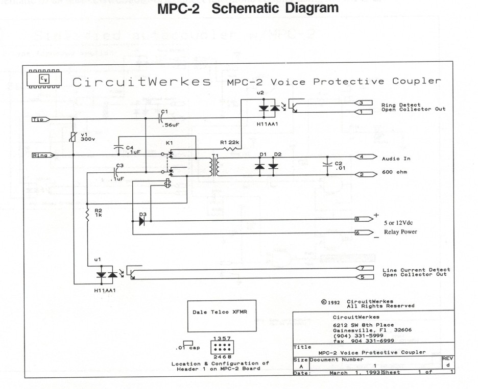
One thing that I felt I never quite mastered, even after all of my telephone projects, was the actual interface to the telephone line. For this project I did use a circuit that was supposed to be "part 68 compliant", and provided the off hook signal. It didn't work too well however. Every now and then I'd get a false off hook indication. That's still my big problem today.
My initial goal with this project was to implement several telephony features, and perhaps eventually an answering machine. I eventually came to the conclusion that I'd get there faster, and more efficiently, if I based the project around a PC with a voice modem. I eventually went this route, using a US Robotics Sportster Voice modem, the USR5695. I generally refer to this project as my CID-PC.
Have any surplus 8051 microcontrollers ?